My OptiSmart arrived this afternoon from Current Cost and I immediately dismantled it :)
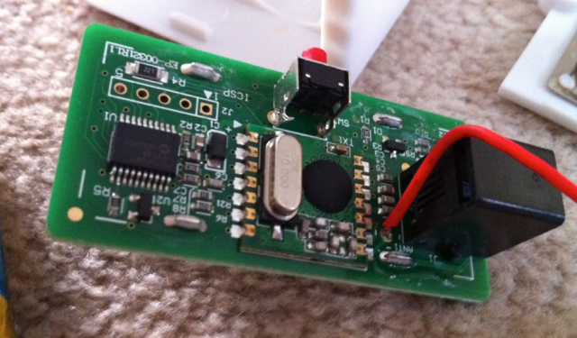
Fairly amusing to see how tiny the circuitry was, and that the batteries are taking up 80% of the space inside the device!
The board itself looks pretty straight forward (although my knowledge is pretty limited in this area). I can see the RF module and a PIC chip with what appears to be a header available for reflashing?
My gas meter has an RJ11 connector with 2 wires staying open about 80% of the dial on the meter then closing for the remaining 20%. I hoped to replace the standard sensor with a straight forward RJ11 cable.
I spliced into the cable which comes with the OptiSmart (to read the blinking LED from newer meters) but couldn’t determine what each of the 4 wires in the sensor cable was doing. *EDIT* Upon further investigation, it appears the green wire is GND and red is +3V. Shorting any combination of them didn’t seem to count a pulse on the EnviR display so it doesn’t look like I can connect it to my gas meter as simply as I was hoping. *EDIT* Cracked it :) Join the green and brown wires then place the reed switch between the red and black wires- voila!
I need to adjust it to convert from cubic feet of gas consumed to the equivalent watts but then i’m all set!
I will likely try more experimenting tomorrow- worst case scenario I guess I could fashion a circuit which blinks an led on the opening or closing of the RJ11 connection but it seems a bit mad to need to go that route!
L


Thanks for posting this. Helps me qas we are still waiting for Optismart to be released in Australia.
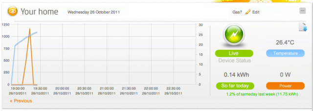
I should add that the results have been a bit sketchy. I have a feeling if the gas stops flowing whilst the reed switch is closed the OptiSmart is reading this as continuous blinking so goes a bit “off the chart”. I may need to build a tiny circuit to create a pulse from just the rising or falling edge.
This is a known bug ewith the optismart. CC say it is or will be fixed in the latest version I think